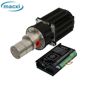

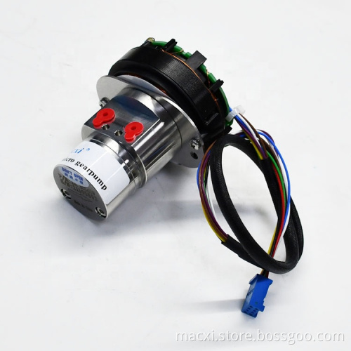


Stainless steel micro electromagnetic driven pump
-
$208.30≥1 Piece/Pieces
- Min. Order:
- 1 Piece/Pieces
- Min. Order:
- 1 Piece/Pieces
- Transportation:
- Ocean, Land, Air
- Port:
- Shanghai
Your message must be between 20 to 2000 characters
Contact Now| Place of Origin: | china,jiangsu |
|---|---|
| Productivity: | 50000/year |
| Supply Ability: | 50000/year |
| Payment Type: | T/T |
| Incoterm: | FOB,CFR,EXW |
| Certificate: | ISO 9001 |
| HS Code: | 8413609090/8443992990/8413910000 |
| Transportation: | Ocean,Land,Air |
| Port: | Shanghai |
Attentions:
1.400 Mesh filter shall be installed at the inlet of gear pump.
2.This gear pump is suitable for continuous operation for a long time and can not be used under the condition of frequent start and stop.
3.Before using, squeeze in a small amount of medium to lubricate the gear from the gear pump inlet.
Product Model Selection Instruction:
|
Pump Head |
Motor |
||
|
I |
0.07 |
S |
40W |
|
"I" means the Integrated Structure |
Pump revolution, Unit: ml/rev, note ① for details |
Pump body materials, note ② details |
Motor type and Power |
Notes:
1. Pump output volume: 0.07,0.15,0.3,0.6,0.9,1.5,3.0,6.,12.0 (Unit: ml/rev)
2."S" means pump body material is 316L, gear and shaft sleeve are PEEK, seal with PTFE, the rest others are 316L.
"T" means pump body material is 316L, gear and shaft are Tungsten steel, shaft sleeve is PEEK, seal with PTFE, the rest others are 316L.
"P" means pump body material is PPS, gear materail and shaft sleeve are PEEK, seal with FFKM, the rest others are Hastelloy.
"H" means the pump body materials is Hastelloy, the gear and shaft sleeve is PEEK, the seal materials is PTFE, the rest of the pump flow material is Hastelloy, the appearance and size is same as 316L pump, details product parameters refer to 316L pump head.
Product Model : I0.30S40W
Product Diagram:

Product Parameters:
|
Pump Model |
Motor Type |
L1(mm) |
L2(mm) |
Pressure(bar) |
Weight(kg) |
Rated Current(A) |
Imp.&Exp. Size |
Flow(L/H) |
|
I0.07S |
40W |
93.1 |
30.5 |
8 |
0.77 |
2.5 |
G1/8 |
2.1~18.9 |
|
I0.15S |
95.4 |
32.8 |
0.77 |
4.5~45 |
||||
|
I0.30S |
95.4 |
32.8 |
0.77 |
9~90 |
||||
|
I0.60S |
95.8 |
36.9 |
4 |
0.78 |
18~180 |
|||
|
70W |
108.1 |
36.9 |
8 |
0.93 |
3.3 |
18~180 |
||
|
I0.90S |
113.1 |
41.9 |
4 |
0.94 |
27~270 |
|
Pump Head Parameters |
Motor Parameters |
Motor wiring definition |
|||
|
Fluid Viscosity |
0.2-1500cps |
Drive Type |
Built in drive DC brushless |
Red |
+24V |
|
AAmbient TemperAture |
-40℃-70℃ |
Rated Voltage |
24V |
Black |
0 |
|
Static sealing |
PTFE |
Speed regulating voltage |
0-5 (0.35V ON 0.3V OFF) |
Brown |
Speed control signal 0-5V input |
|
Pump Body |
316L |
Speed rpm |
500-5000rpm |
||
|
Gear |
PEEK、316L |
Working system |
Continuous |
Blue |
square wave, 2 pulses per |
The values in this table are for reference only.
Remarks:
OEM service are avaiable according to your request.
The specifications are only for reference, for details checking, please feel free to contact us.

40W Motor Instruction
Motor parameter
(Number of phase)
N
3
(Rated Voltage)
VDC
24(8-30VDC)
(Rated Power)
W
40W
(Speed regulating voltage)
VDC
0-5 (0.35V ON 0.3V OFF)
(Range of speeds)
RPM
500-5000
(Maximum current)
A
2.2A
(Instantaneous protection current)
A
5A
(Number of phase)
N
3
(Rated Voltage)
VDC
24(8-30VDC)
(Rated Power)
W
40W
(Speed regulating voltage)
VDC
0-5 (0.35V ON 0.3V OFF)
(Range of speeds)
RPM
500-5000
(Maximum current)
A
2.2A
(Instantaneous protection current)
A
5A
Wiring instructions
|
Red |
+24VDC |
|
Black |
GND |
|
Brown |
Speed control signal 0-5V input |
|
Blue |
5V level, square wave, 2 pulses per revolution |

Secure features
Operation protection: when the motor running current reaches the limit current of 2.2A, the motor drive will start the protection and stop running.
Locked rotor protection: when the pump body is locked, the drive will start the protection function and cut off the internal power supply of the motor.
Software / hardware over-current protection: when the system detects that the instantaneous current of software and hardware inside the motor is greater than 5a, the drive will start the protection.
Hall error protection: when the motor Hall sensor failure, the motor will start protection stop running, to prevent burning the motor.
Under voltage protection: when the operating voltage is lower than the specified range, it will stop operation.
Performance data
 Note:The valve door is fully opened and tested under no-load condition
 Note:The valve door is blocked and tested under full load conditio

Related Keywords
-

SS pigment inks Micro Magnetic Drive Gear Pump

Brushless DC magnetic drive gear pump

Brushless self priming dc pump
Related ProductsProduct Categories-
Integrated Gear Pump(68)
-
Stainless Steel Gear Pump(282)
- Stainless Steel 0.07ml/rev Gear Pump(35)
- Stainless Steel 0.15ml/rev Gear Pump(19)
- Stainless Steel 0.30ml/rev Gear Pump(30)
- Stainless Steel 0.60ml/rev Gear Pump(25)
- Stainless Steel 0.90ml/rev Gear Pump(32)
- Stainless Steel 1.50ml/rev Gear Pump(58)
- Stainless Steel 1.50ml/rev (72specs) Gear Pump(17)
- Stainless Steel 3.00ml/rev (72specs) Gear Pump(25)
- Stainless Steel 3.00ml/rev Gear Pump(13)
- Stainless Steel 6.00ml/rev Gear Pump(13)
- Stainless Steel 12.00ml/rev Gear Pump(15)
-
wear-resisting Gear Pump(39)
-
Control System Of Gear Pump(9)
-
Hastelloy Materials Gear Pump(159)
- Hastelloy 0.07ml/rev Gear Pump(22)
- Hastelloy 0.15ml/rev Gear Pump(12)
- Hastelloy 0.30ml/rev Gear Pump(18)
- Hastelloy 0.60ml/rev Gear Pump(16)
- Hastelloy 0.90ml/rev Gear Pump(14)
- Hastelloy 1.50ml/rev Gear Pump(16)
- Hastelloy 1.50ml/rev (72 Specs) Gear Pump(17)
- Hastelloy 3.00ml/rev (72 Specs) Gear Pump(15)
- Hastelloy 3.00ml/rev Gear Pump(9)
- Hastelloy 6.00ml/rev Gear Pump(11)
- Hastelloy 12.00ml/rev Gear Pump(9)
-
PPS Materials Gear Pump(19)
-
Pneumatic Diaphragm Pump(36)